
How to Turn a Photo to a 3D Model: A Designer's Guide
Convert photos and sketches to 3D models with photogrammetry, AI tools, and camera setup best practices.

You sketch dozens of concepts, but only a few ever reach 3D because modeling each one takes too long.
Photo-to-3D conversion changes that by generating rotatable geometry from photos and sketches in minutes. You can check proportions from every angle during ideation, capture physical prototypes digitally, and produce client-ready visualizations from an ordinary camera.
This guide covers how the technology works, what you need to know about preparing photos, which approaches match different design phases, and how to get results worth showing to clients.
How Photo-to-3D Conversion Works
Photo-to-3D conversion turns your photographs into three-dimensional geometry.
You give the software images, it finds distinctive features like edges and texture patterns, then calculates where those features sit in 3D space.
Then, you get a mesh (a connected surface made of polygons) with texture information pulled from your original photographs.
Three methods handle this, each suited to different stages of a design project.
Photogrammetry works through geometric triangulation. You shoot multiple overlapping photographs from different angles.
The software figures out where your camera was for each shot, then traces sightlines from matching feature points until they intersect in 3D space. This gives you measurement-accurate results you can feed directly into manufacturing workflows.
Neural Radiance Fields (NeRF) use a neural network that learns a continuous 3D representation from your images. The AI interpolates what your object should look like from any viewing angle, even positions you didn't photograph.
You get highly photorealistic output built for visualization and client presentations, but rendering each view takes time.
3D Gaussian Splatting solves that speed problem. It uses millions of Gaussian ellipsoids that GPUs can process in parallel, making real-time or near-real-time rendering possible where NeRF would have you waiting.
Photogrammetry fits when you need dimensional accuracy for reverse engineering, CAD-compatible geometry, or manufacturing.
NeRF and Gaussian Splatting work better during visualization and concept development, where how the render looks matters more than exact measurements.
What about sketch-to-3D?
These three methods all start from photographs. But if you're earlier in the design process and working from sketches or renderings rather than photos of physical objects, a different approach makes more sense.
Vizcom Make 3D generates textured meshes directly from 2D renderings on your canvas, skipping the photography setup entirely. You stay in the same workspace where you sketched the concept, and you're evaluating it in three dimensions seconds later. This keeps your iteration loop tight during the phases where creative momentum matters most.
How to Convert Photos to 3D Models
Converting photos to 3D follows a structured workflow across five stages. Each stage has specific requirements depending on your downstream application and current design phase.
Stage 1: Capture and Preparation
For photogrammetry, shoot multiple overlapping photographs from different angles with consistent lighting. Your image set should cover the object completely (front, back, sides, top, and bottom when possible).
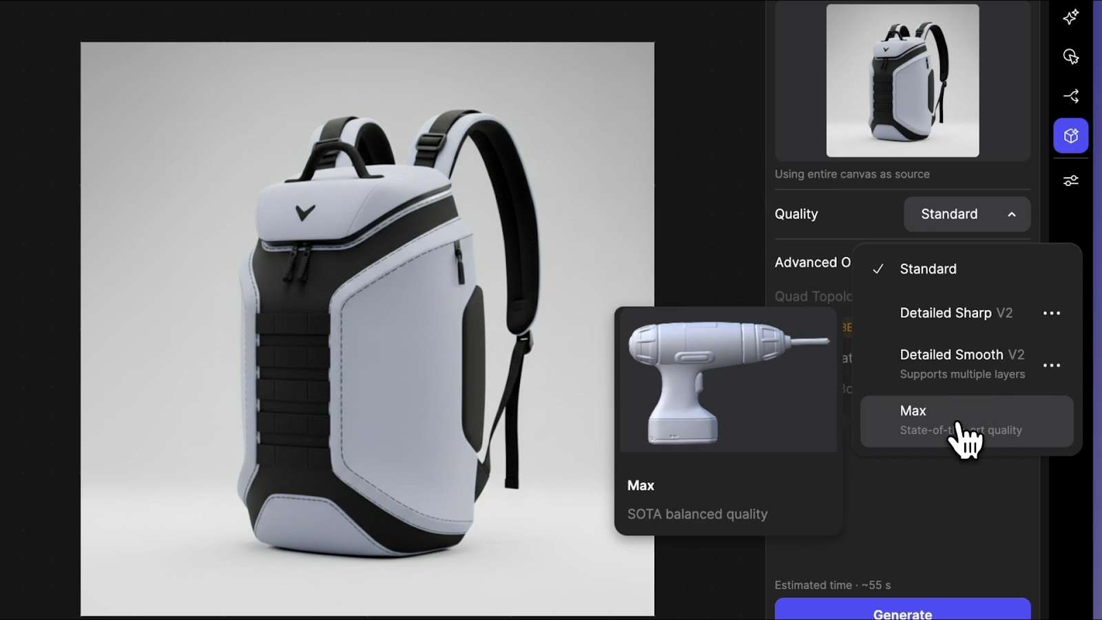
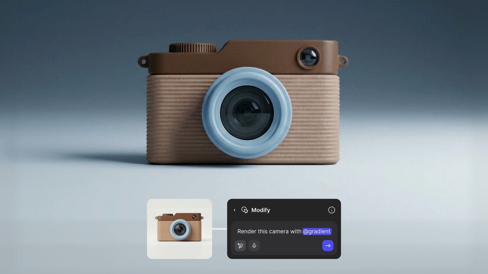
For sketch-based or rendering-based workflows, you skip the photography setup. In Vizcom, place a rendering on the canvas and select Generate 3D from the toolbar or the layers panel. You choose from several 3D generation modes depending on what you need:
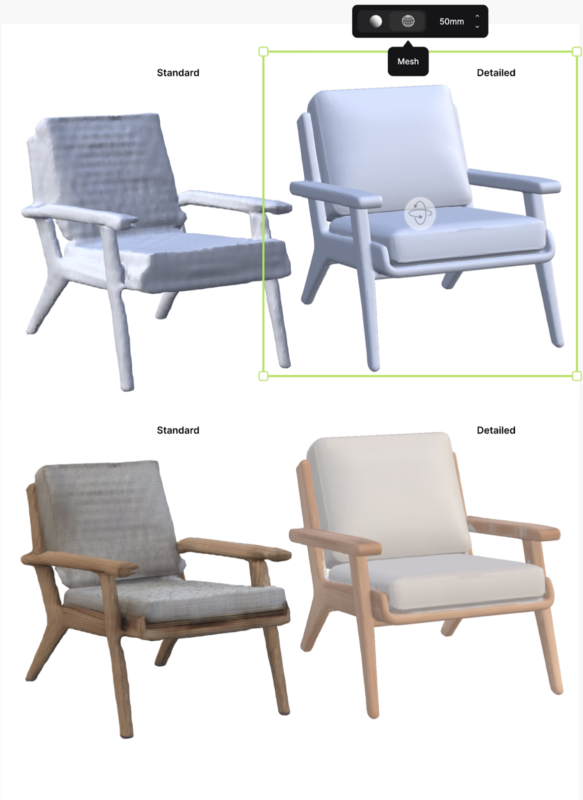
- Standard is speed-first, lower resolution, and good for quick form checks when you're still narrowing direction
- Detailed Smooth produces cleaner topology suited for exporting to your 3D editing program
- Detailed Sharp preserves intricate surface details in both mesh and textures, useful when you want to see how a specific detail reads in three dimensions
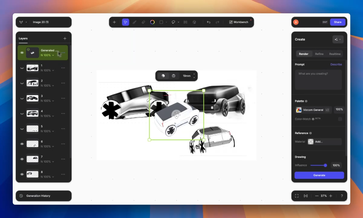
Vizcom separates your concept from the background automatically and generates the model as a new layer. You can work from line drawings, sketches, or photographs, so you start with whatever format matches your current phase.
Can you use multiple views for better results?
Yes. Vizcom Multiview to 3D lets you select 2 to 5 visible sketch layers showing the same object from different perspectives, then generates a combined 3D model with more control over the final output.
Vizcom’s New View feature also allows you to generate multiple angles of a design, helping you better communicate intent, refine proportions, and maintain visual consistency without redrawing. After generating multiple views of the object, you can use Make 3D to turn them into 3D models.
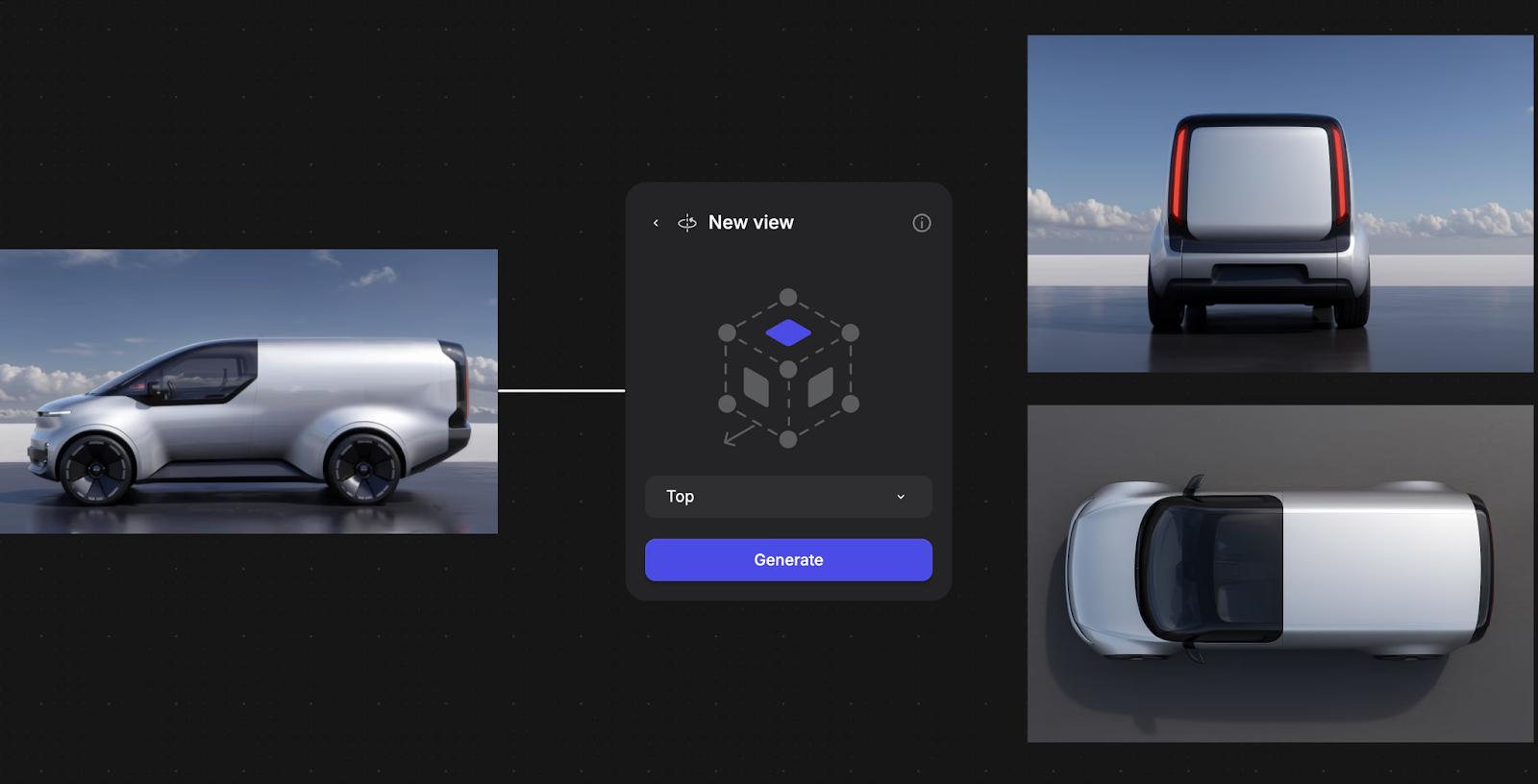
Think of your object as a cube and provide sketches that describe its key faces from different angles. For more variation, use sketches with differences on the same theme. The 3D generation chooses which features to keep, and you can regenerate to get different combinations.
This connects directly to the multi-view photography principles covered earlier in this article, except you're working from sketches and renders rather than photographs.
The same logic applies. More angles give the system more information to work with.
Stage 2: Processing and Initial Model Generation
For photogrammetry workflows, the software handles feature matching across images, camera calibration, triangulation, and mesh generation.
This produces a point cloud (thousands of dots describing the surface), connects those points into a continuous mesh, and applies texture information from your original photographs.
In Vizcom, processing works differently. The AI interprets your 2D input and generates corresponding 3D geometry directly. You get a rotatable textured mesh you can evaluate from all angles.
The model appears as a layer on your canvas, which means you can sketch over it, use it as an underlay for new ideas, or set up rendering scenes from it without leaving the workspace.
Stage 3: Evaluation and Rendering Scenes
Once you have geometry, evaluate it. Check that important design features are captured correctly. Confirm proportions hold up when rotated through 360 degrees. Then, look for gaps or thin features that need attention.
In Vizcom, clicking the 3D layer gives you bounding box controls for scaling and orbit controls for inspecting from different angles.
A focal length slider lets you check how proportions read at different camera distances. This is important for automotive forms where lens compression changes how a fender line reads, or for furniture where you need to confirm that a chair's proportions feel right at the human scale rather than just looking correct in a wide-angle view.
The real workflow advantage comes from what happens after evaluation. Duplicate the 3D layer, set up a different viewing angle on the same canvas, then use the Describe function to generate photorealistic renderings from your 3D scene.
You go from sketch to 3D model to client-ready rendering without switching applications.
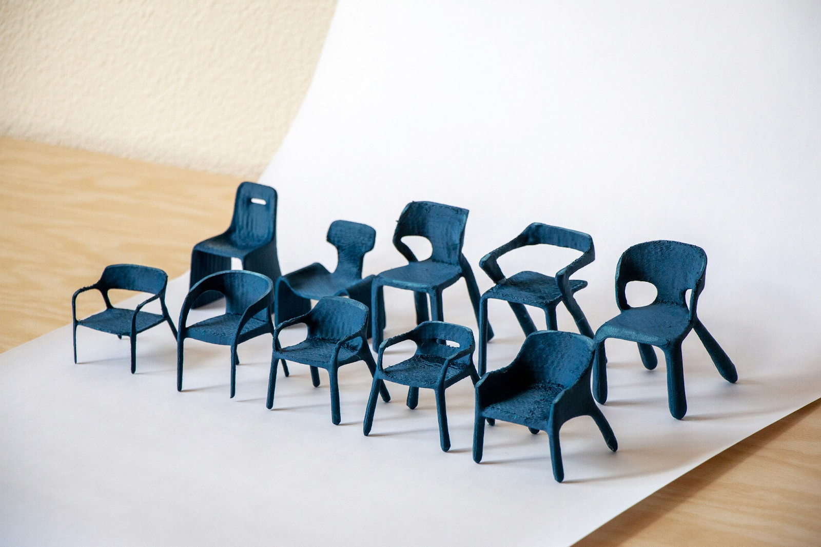
Designer Chris Ference used this kind of loop — sketching, generating 3D, evaluating, then rendering from new angles — to move from initial concept to 3D-printed chair iterations in 48 hours.
Stage 4: Export and Application
Export formats depend on where the model goes next.
- 3D Printing requires STL or OBJ formats with watertight mesh geometry
- Product Visualization uses high-poly models with full texture sets to preserve surface detail
- Manufacturing Integration needs STEP or IGES formats that work directly with engineering systems (these require dedicated CAD software, not photo-to-3D tools)
- Real-Time Applications use lightweight FBX or glTF formats with reduced polygon counts for gaming engines or AR previews
Vizcom exports high-density triangulated meshes in .glb (which carries textures), .obj, .stl for 3D printing, and .usdz for AR display on iPads. The .usdz export is particularly useful for checking scale and proportion in physical space.
You can view your concept at actual size in the room where it would live before committing to a physical prototype.
Choosing Approaches for Different Design Phases
Early Concept Development
Speed matters more than precision. You're sketching dozens of directions and need to know which ones hold up in three dimensions before spending time on any of them.
Vizcom 3D generates a textured mesh from any 2D rendering on your canvas. Standard mode handles quick form evaluation. Detailed Sharp shows you whether a specific surface detail works.
Either way, you're seeing your concept from all angles within seconds, not hours into a CAD session.
If you're exploring variations on a theme, Multiview to 3D lets you feed in multiple sketch perspectives of the same concept for a more controlled output.
You can regenerate to get different combinations of your design features, which makes this a tool for creative exploration rather than just documentation.
Mid-Stage Development
Accuracy starts to matter more. Multi-view photogrammetry captures existing physical prototypes — foam models, clay mockups, or early fabrications — for digital refinement. This lets you work in whichever medium feels most productive without losing design information when switching between physical and digital.
At this stage, Vizcom Detailed Smooth mode produces geometry with clean enough topology to export directly into your 3D editing program for further refinement.
You're no longer just checking form. You're building on it.
Production Phases
Precision becomes critical. Multi-view photogrammetry from overlapping photographs provides measurement-accurate geometry suitable for manufacturing workflows.
You need models that work directly with engineering systems, maintain exact dimensions, and support downstream processes like tooling design and production planning.
Photo-to-3D tools and AI-generated meshes aren't substitutes for production CAD at this stage, but they can accelerate the path to getting there.
Faster Iteration Where It Counts
Photo-to-3D conversion removes the bottleneck of committing hours to 3D modeling before knowing whether a concept has potential.
The concepts that reach detailed development are the ones you've already validated visually, which means less time refining directions that don't hold up when you rotate them.
With Vizcom, the loop gets even tighter. You sketch on the canvas, generate a rendering, convert it to 3D, evaluate the form from every angle, set up a new view, and generate a photorealistic scene — all in the same workspace.
That speed supports the kind of creative experimentation where you're pushing through dozens of directions rather than committing to two or three too early.
The messy middle of design iteration is where the strongest concepts emerge, and staying in that space longer is how you find them.
Spend less time modeling and more time designing. Sign up to experience Vizcom firsthand.
Explore
Explore more blog posts & resources to get inspired
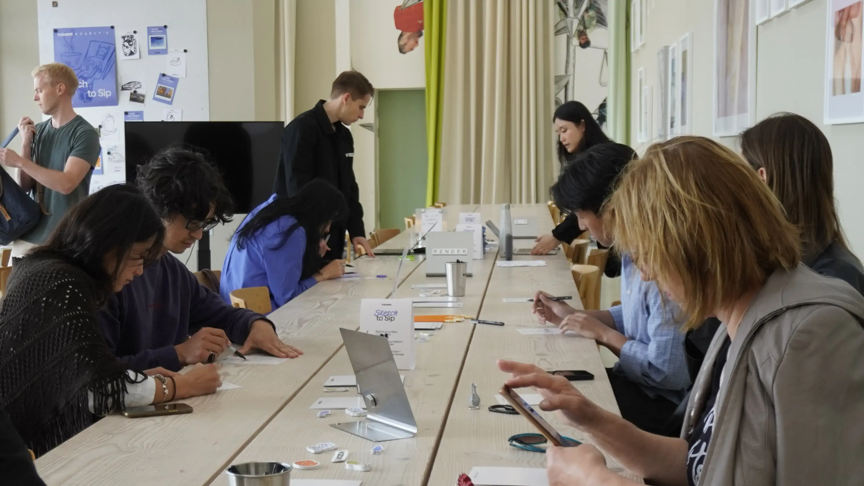
For one day during 3DaysofDesign in Copenhagen, Darcy's Cafe ran on a different currency — a sketch. Draw it, we'd render it live in Vizcom, and you'd walk out with a print — coffee included.
See how Kohler's industrial design team uses Vizcom to save time, speed up workflows, and create better work.
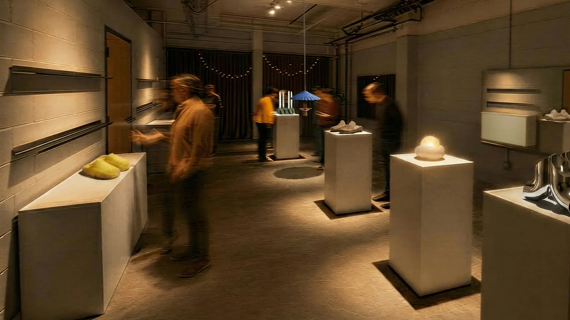
Explore the designs of Vizcom's San Francisco Design Week exhibition where furniture, footwear, lighting, and automotive concepts come to life through AI-powered visualization. Follow along as designers share the stories, sketches, and tools behind every piece on display.
Frequently asked questions
Yes of course! Our starter plan is completely free, no credit card required. This is a great plan to explore vizcom with.
We accept all major credit and debit cards.
Admins (paid) – can edit files, manage workspace settings, billing, teams, and invite members. Editors (paid) – can edit files but not manage settings, billing, or teams. Viewers (free) – can only view files in read-only mode.
Team billing is handled centrally by the Admin. All paid seats, whether Admins or Editors, are included in a single invoice under the same billing cycle, while Viewers remain free and do not affect the cost.
Yes, you can. An Admin can update the plan in the billing settings, and the switch will take effect on the next billing cycle at the annual rate.
Yes, you own everything you create in Vizcom. For free users, while Vizcom may use generated images to improve its services, it does not claim ownership of your designs, concepts, or original ideas—you keep full rights to them. For paid users, your images and designs remain entirely private and are only used to deliver the service. Every design, concept, and image you create or upload is fully yours and kept confidential.
Vizcom does not use your data to train AI models if you’re on a paid plan. Everything you create stays private and is only used to provide the service. Free users may have their generated images included to help improve Vizcom’s services, but even then, Vizcom does not claim ownership of your designs, concepts, or original ideas—you retain full rights.